Progress at the Rocket Factory
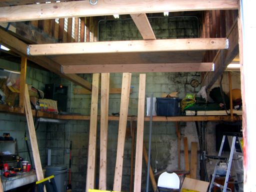
We’ve erected the new floor beam and hung three joists. There are ten more joists to hang, but we’ve done the hardest part of the work now.
We’ve erected the new floor beam and hung three joists. There are ten more joists to hang, but we’ve done the hardest part of the work now.
Mars Saxman

2006: January February March April May June July August September October November December
2005: January February March April May June July August September October November December
2004: January February March April May June July August September October November December
Wanderings in Black and Red (previous site)
Not to be critical, but what material(s), dimensions and attachment points make up the beam on the left of the joists?
Comment by Lewis Gardner — April 28, 2008 @ 11:01 pm
It is a pressure-treated 4×6, each end supported by a 4×4 post. The beam is secured to each post with a pair of inside corner plates. The post against the back wall rests on the concrete wall footing and is anchored to the floor and to the wall using L-braces and masonry bolts. The post against the front wall sits on an existing pier used for the main door framing, and is attached to the post supporting the door header using L-braces and tie plates.
Comment by mars — April 29, 2008 @ 7:25 am
The good part is that it sounds like the 4×6 isn’t going to move at the ends.
The thing that concerns me is load carrying capacity is related to the depth of a beam. While width helps keep the beam from rotating under stress it does not help as much with deflection. In general joists attach to beams of a greater depth since the beam is carrying the load of many joists. When I see 6x joists attached to a 6x beam I wonder about how the sizing was done.
My guess is that your loft is approx 8’x16′ which at 40 pounds per square foot (evenly distributed light storage) would give a total load of 5,120 pounds. This means that the 4×6 needs to be able to carry 2,560 pounds. I can’t find my Army construction field manual but one of my old spreadsheets named beamsizing.xls gives a max load of a 16′ 3.5″x5.5″ wood beam as 2,316 pounds. That sounds optimistic to me but it could be in the ballpark.
Where the formula (((3.5*5.5)*(3.5*5.5))/16)*100=2316.016 came from I have no idea and it does not account for width vs depth. It looks like a WAG factor to me.
Anyway. You need to keep an eye on the deflection of the 4×6 beam as you start to load the loft. If deflection gets excessive you will need to add some additional support. This could be additional post(s) below the 4×6, bolting a piece of steel (flitch beam) to the side of the 4×6 or adding another 4×6 below and scabbing the two together with 1/2″ plywood on the sides.
My previous garage didn’t have a beam for pulling engines so I placed a 3″ steel pipe across 6 rafters. To check deflection I marked an X on the floor and used a pair of sticks on a rocking motion to find the distance between the floor and bottom of the rafters without a load. When I picked up an fairly large fully rigged V8 marine engine to where it just hovered above the truck bed the deflection was less than 1/4″ and I felt safe in proceeding without additional support.
How much deflection is too much? Hard to say. One number I have seen is 1/360 of the span. So if the 4×6 is 16′ long then about 1/2″ of deflection is when to start looking at options.
Best of luck!
Comment by Lewis Gardner — April 29, 2008 @ 9:55 pm
Thank you, that is very interesting.
The loft is indeed 16′ long (though it is actually 8’6″ wide, which is really annoying). I wanted to use a 4×8 beam, but we were unable to find one longer than 10′. We looked into methods of joining shorter pieces to cover a longer span, but decided that we were more likely to be successful at reinforcing a single, shallower beam than at joining two deeper ones. We have not done anything to reinforce the beam yet, but my idea was to mount a hanger rod in the center and attach it to the 4×10 ceiling beam immediately overhead.
We would prefer not to add another support post as the beam stretches across our main work area. I like your suggestion of a “flitch beam”; I have never heard of that technique and will read up on it.
Comment by mars — April 30, 2008 @ 10:34 am
I would strongly discourage attachment to the roof structure without consulting an engineer. You get a good bit of snow and the 10″ ceiling beam was designed with that in mind.
I use flitch beams since they are easy, cheap and can be used to reinforce existing beams. The best reference I have come across can be found here: http://www.toolbase.org/PDF/DesignGuides/flitchplate.pdf. For your purpose lagscrewing a 8″x3/8″ steel plate or channel on the outside of the 4×6 would probably work since lateral deflection will be minimal.
If you have need in the future also look at gluelam beams for this sort of thing. The table at http://www.timberweld-southwest.com/Downloads/df_27-tw.pdf seems to indicate a 3 1/8″ x 9″ to be the minimum for around 40lbs/ft2. If you compare the width to depth ratios you will see that depth of the beam really increases the load capacity. Doubling the depth of a 3 1/8″ x 6″ x 15′ to 12″ gains close to a 8X increase in capacity. However doubling the width of a 3 1/8″ x 6″ x 15′ to 6 3/4″ only gains a 2X increase in capacity.
8’6″ is truly annoying!
Comment by Lewis Gardner — April 30, 2008 @ 12:02 pm